|

Author
Text
")

02/08/2019 10:24PM
Goal:
Make a custom canoe seat to add performance and all-day comfort to the canoe, and perhaps loose some weight. Also, to enjoy the build and maybe learn a few things.
Design:
Molded tractor-style seat. Carbon Fiber. On a sliding pedestal to shift weight and facilitate the *very* occasional kneel. Deep seat to keep me stable, with some sort of back lip. Not a back rest, or even back support- but something to counter pushing on the footbrace and keep me from sliding backward. I occasionally paddle long days and want something as comfortable as possible. I have had trouble in the past with soreness after a few hours.
Inspiration:
The seat with Andy Triebold's name on it sold by Savage River looks promising in terms of overall shape. I like the high back, and the coccygeal cut-out. Alan Gage has made a nice pedestal design(google search for it)- I might make an iteration of that slider.
Custom means something made to fit the exact size and anatomy of my posterior. That should go a long way towards comfort, too. The build plan is to make an impression of my backside, fair it, and use it to make a fiberglass mold. Then, use the fiberglass mold with epoxy vacuum infusion to create a lightweight and strong carbon fiber part.
"Everybody needs beauty as well as bread; places to play in and pray in, where nature may heal and give strength to body and soul" -John Muir
02/09/2019 12:32PM
So, it seems rather silly, but I have thought for far too long about the best way to make a mold of my backside. Ideas involving sand or mortar seemed messy, and might have to wait until warmer weather. The simplest thing I came up with was using a few layers of plaster cast material. But how to mold it?
After wondering if my wife would actually agree to help lay plaster across my posterior, I thought that it would be very difficult to do while I was bent in a seated position. And shouldn't the mold be in the shape of my butt while I was actually sitting on it? The method I came up with was to cover a memory-foam pillow with a garbage bag, lay the plaster on that, and sit down until it hardened.
It worked- sort of.
It was very close to the exact size, and had a very anatomic contour. The mold had a couple big wrinkles in the plaster though, and wasn't entirely symmetric. I didn't think I'd be able to evenly fair it out on each side, so I had to look for another solution.

Things then got a little techy, but put to use some skills I'd learned this past year.
Using the mold as a template, I took measurements and modeled a CAD version of a seat in Fusion 360. I could keep the important parameters in place while smoothing the curves and keeping each side exactly symmetric. I radiused the major curves slightly larger than my plaster mold to account for a pad or two being glued over the finished seat. Rowing seats have holes for the ischial tuberosities, and their optimum spacing and size for adult men has been pretty well established. My pedestal sliders will be directly beneath this portion, so I might not make an actual hole, but these areas will be the deepest point of the contour. Some research on coccyx vertebral anatomy and I could model an appropriately sized cut-out. The seat is 13.5" wide and 11" long.
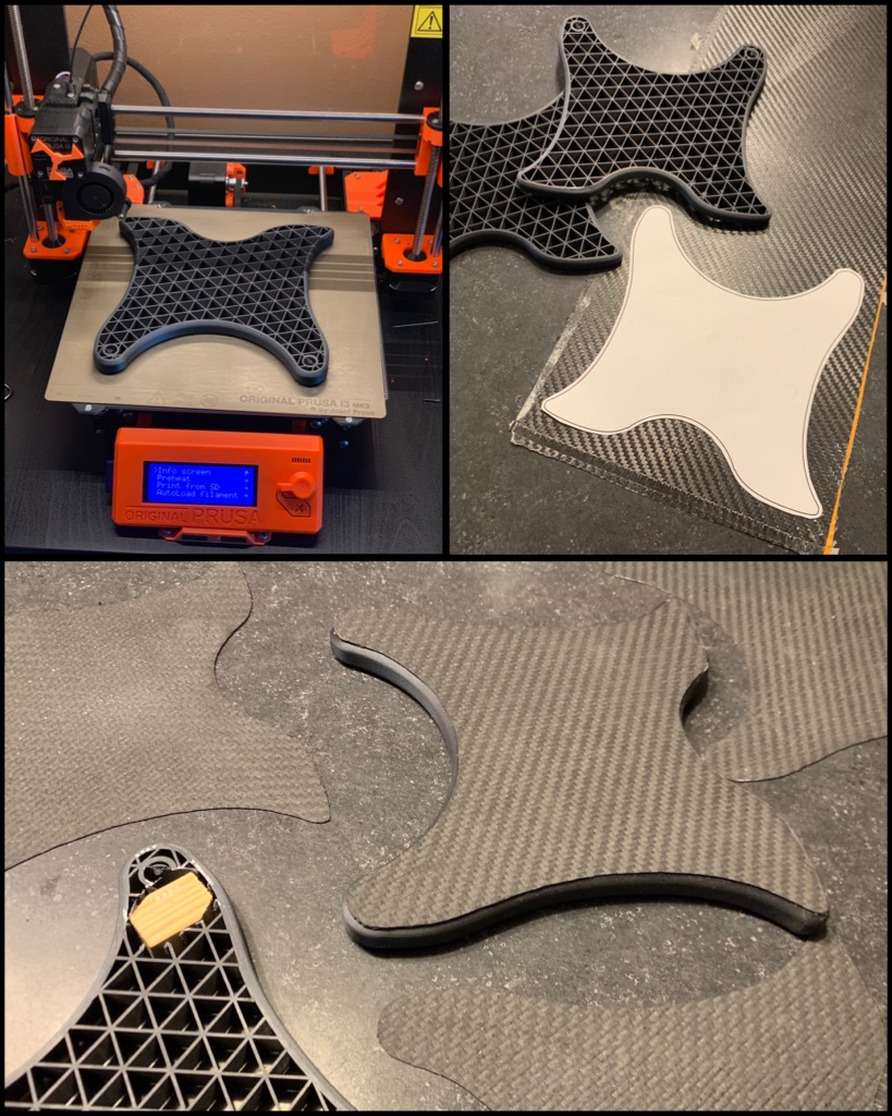
 My 3D printer has a build area of 9x9x10 inches, so I would have to print this in sections and glue them together. I sliced the model in quarters and added 3/8" holes so I could key the sections together with pieces of a wooden dowel.
Knowing that I'd have to fair it anyway, I used a really coarse resolution to speed up printing time. A total of about 18 hrs print time and it came out fairly well. I sat on it and it feels perfect. Next is gluing the sections together and making the surface fair.


After wondering if my wife would actually agree to help lay plaster across my posterior, I thought that it would be very difficult to do while I was bent in a seated position. And shouldn't the mold be in the shape of my butt while I was actually sitting on it?
 The method I came up with was to cover a memory-foam pillow with a garbage bag, lay the plaster on that, and sit down until it hardened.
 It worked- sort of.
It was very close to the exact size, and had a very anatomic contour. The mold had a couple big wrinkles in the plaster though, and wasn't entirely symmetric. I didn't think I'd be able to evenly fair it out on each side, so I had to look for another solution.

Things then got a little techy, but put to use some skills I'd learned this past year.
Using the mold as a template, I took measurements and modeled a CAD version of a seat in Fusion 360. I could keep the important parameters in place while smoothing the curves and keeping each side exactly symmetric. I radiused the major curves slightly larger than my plaster mold to account for a pad or two being glued over the finished seat. Rowing seats have holes for the ischial tuberosities, and their optimum spacing and size for adult men has been pretty well established. My pedestal sliders will be directly beneath this portion, so I might not make an actual hole, but these areas will be the deepest point of the contour. Some research on coccyx vertebral anatomy and I could model an appropriately sized cut-out. The seat is 13.5" wide and 11" long.
 My 3D printer has a build area of 9x9x10 inches, so I would have to print this in sections and glue them together. I sliced the model in quarters and added 3/8" holes so I could key the sections together with pieces of a wooden dowel.
 Knowing that I'd have to fair it anyway, I used a really coarse resolution to speed up printing time. A total of about 18 hrs print time and it came out fairly well. I sat on it and it feels perfect. Next is gluing the sections together and making the surface fair.


"Everybody needs beauty as well as bread; places to play in and pray in, where nature may heal and give strength to body and soul" -John Muir
02/20/2019 01:24AM
I've been working at this for an hour at a time or so in the evenings after putting the kids to bed. It's been little steps with lots of waiting/dry time in between. I first glued the printed parts together and faired the surface with a few coats of drywall compound because I had a bucket of premix on hand and it's easy to sand. 
Then, I started painting the surface using random leftover colors of spray paint I had; sanding between each color with 320 grit shows low/high spots. It worked pretty well, but I quickly found out it sure is difficult to smoothly sand concave curves. Using a dry kitchen sponge as a sanding block was one of the more effective tools. I know I could spend way more time surfacing this, and using the right paints, etc... but the final seat will be covered with foam, so I don't care too much that it doesn't come out to a perfect smooth gloss.
Next, I made a flange around the seat by hot-gluing on a piece of clear acrylic plastic. I eased the transition around the edges using plastilene modeling clay. This will make it easier to lay fiberglass and later carbon in the mold, and this part ends up being cut off the final seat anyway, so lumpy clay pressed in with my fingers is good enough. This would make my finished plug. I waxed the whole thing with 5 coats of mcguires #8 release wax, and then sprayed a thin layer of dilute PVA to ensure a good release.
Now, onto the mold itself: I sprayed the plug with a polyester gelcoat. Ive never sprayed gelcoat before. Using a big 2.5mm tip in the HVLP and thinning it 5% with acetone made it work alright. As soon as the gelcoat was firm-tacky, I put on the first layer of 1.5oz fiberglass matt. From there, It's just hand-laying 2-3 layers at a time of the fiberglass matt and mixing in a random layer of some scrap fiberglass cloth I had. Total of 7 layers over the gelcoat, and I used a little more than a half-gallon of polyester resin. I'm leaving this weekend to go ski the Birkie, so it will have a few days to sit around and fully cure.
Next week I'll trim the edges, and see if I can release it from the plug without chipping the gelcoat.


Then, I started painting the surface using random leftover colors of spray paint I had; sanding between each color with 320 grit shows low/high spots. It worked pretty well, but I quickly found out it sure is difficult to smoothly sand concave curves. Using a dry kitchen sponge as a sanding block was one of the more effective tools.
 I know I could spend way more time surfacing this, and using the right paints, etc... but the final seat will be covered with foam, so I don't care too much that it doesn't come out to a perfect smooth gloss.
 Next, I made a flange around the seat by hot-gluing on a piece of clear acrylic plastic. I eased the transition around the edges using plastilene modeling clay. This will make it easier to lay fiberglass and later carbon in the mold, and this part ends up being cut off the final seat anyway, so lumpy clay pressed in with my fingers is good enough.
 This would make my finished plug. I waxed the whole thing with 5 coats of mcguires #8 release wax, and then sprayed a thin layer of dilute PVA to ensure a good release.
 Now, onto the mold itself: I sprayed the plug with a polyester gelcoat. Ive never sprayed gelcoat before. Using a big 2.5mm tip in the HVLP and thinning it 5% with acetone made it work alright.
 As soon as the gelcoat was firm-tacky, I put on the first layer of 1.5oz fiberglass matt. From there, It's just hand-laying 2-3 layers at a time of the fiberglass matt and mixing in a random layer of some scrap fiberglass cloth I had. Total of 7 layers over the gelcoat, and I used a little more than a half-gallon of polyester resin. I'm leaving this weekend to go ski the Birkie, so it will have a few days to sit around and fully cure.
 Next week I'll trim the edges, and see if I can release it from the plug without chipping the gelcoat.

"Everybody needs beauty as well as bread; places to play in and pray in, where nature may heal and give strength to body and soul" -John Muir
03/02/2019 08:41PM
Two steps forward and one step back. And some knowledge gained, I guess.
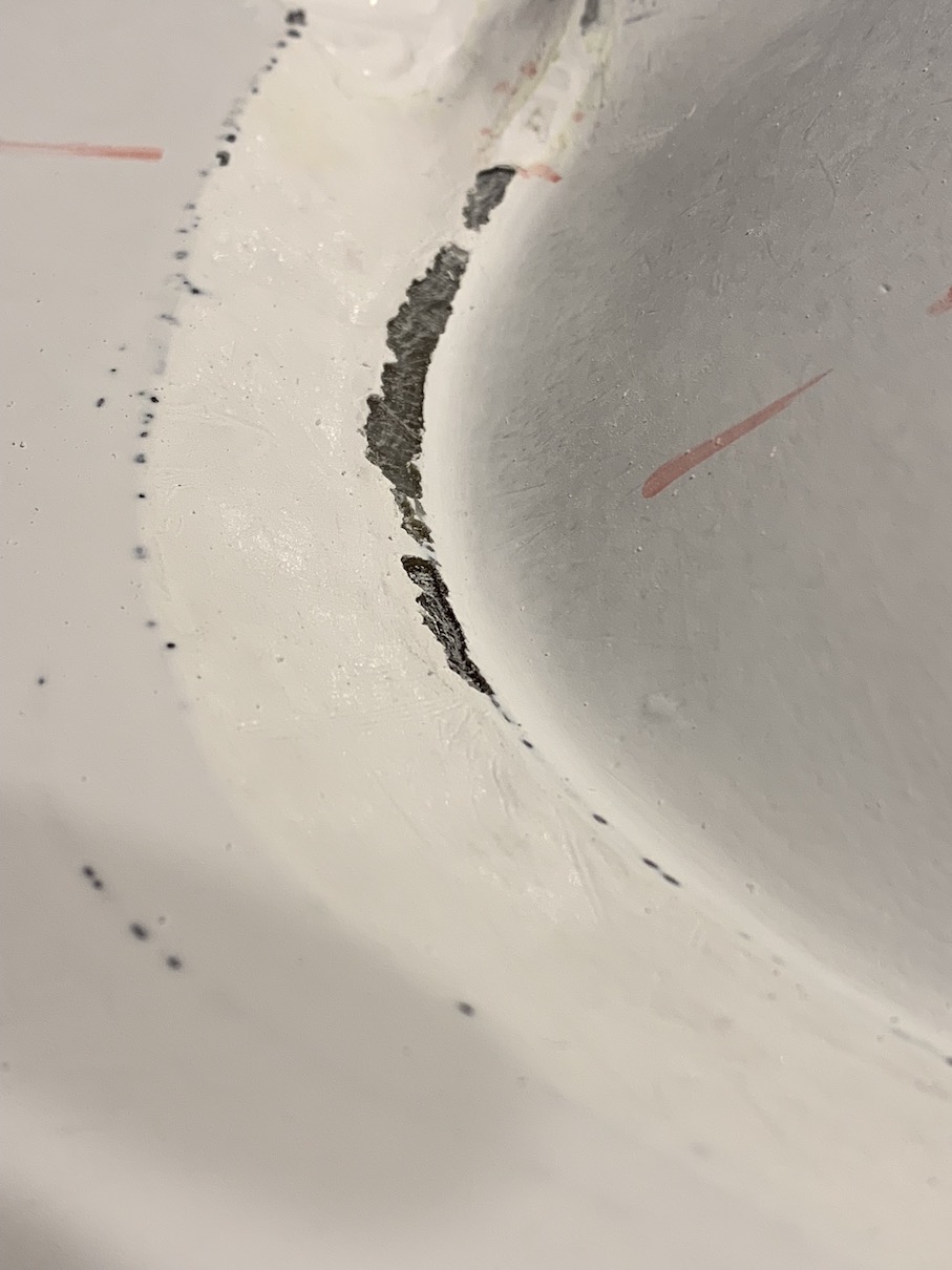
The fiberglass mold released from the plug just fine. It tore the paint off of the drywall mud in two places. I suppose I could repair it if needed, but I shouldn't need the plug anymore. This was my first time spraying gelcoat instead of painting it on, and my major worry was that it would kick off in the gun before I could clean it out. So 1) the gelcoat ended up being a little thin in spots, and you can see some of the fiberglass mat show through it. I think the surface is still perfectly smooth though so it should be fine. 2) the wax and thin PVA layer must not have completely covered the plasticine clay, because all around the clay part there were real bad fisheyes in the gelcoat. Resin from the fiberglass layers filled them in, though, so the surface is smooth and shouldn't be a problem. At first glance, the mold appeared fine.
I soon discovered, though, that there were a LOT of air bubbles trapped between the gelcoat and the first fiberglass mat layer. Probing the mold surface with a metal pick, I could find several pockets of thin gelcoat with an air bubble underneath. This will not be good, as the unsupported gelcoat will stick to any part I make in the mold and likely damage the mold. So I probed around the whole thing and gouged out any pockets I found so that I could fill them in with gelcoat and sand them flush with the surface. These are all the red marks in the photo; each is pointing to a bubble that needs to be filled. The good news is that none of the bubbles seem to be on the actual seat: they are ALL on the edges of the clay where it abutted either the seat or the acrylic flange. So I can fill them and sand them down and it shouldn't affect the surface finish of the seat at all- just the area that will be trimmed off anyway. The actual seat part came out really nice.
I think next time I use clay for a plug, I will cover it with some sort of body filler or surfacing paint or something instead of just putting wax and PVA right onto the clay. And I will take extra care to get out all the bubbles in the first fiberglass layer right on top of the gelcoat. Lesson learned, but I think this mold will still be fine.
Bubbles have been excavated, masked off, filled with gelcoat resin, and left to cure.
The fiberglass mold released from the plug just fine. It tore the paint off of the drywall mud in two places. I suppose I could repair it if needed, but I shouldn't need the plug anymore. This was my first time spraying gelcoat instead of painting it on, and my major worry was that it would kick off in the gun before I could clean it out. So 1) the gelcoat ended up being a little thin in spots, and you can see some of the fiberglass mat show through it. I think the surface is still perfectly smooth though so it should be fine. 2) the wax and thin PVA layer must not have completely covered the plasticine clay, because all around the clay part there were real bad fisheyes in the gelcoat. Resin from the fiberglass layers filled them in, though, so the surface is smooth and shouldn't be a problem. At first glance, the mold appeared fine.

I soon discovered, though, that there were a LOT of air bubbles trapped between the gelcoat and the first fiberglass mat layer. Probing the mold surface with a metal pick, I could find several pockets of thin gelcoat with an air bubble underneath. This will not be good, as the unsupported gelcoat will stick to any part I make in the mold and likely damage the mold. So I probed around the whole thing and gouged out any pockets I found so that I could fill them in with gelcoat and sand them flush with the surface. These are all the red marks in the photo; each is pointing to a bubble that needs to be filled. The good news is that none of the bubbles seem to be on the actual seat: they are ALL on the edges of the clay where it abutted either the seat or the acrylic flange. So I can fill them and sand them down and it shouldn't affect the surface finish of the seat at all- just the area that will be trimmed off anyway. The actual seat part came out really nice.
I think next time I use clay for a plug, I will cover it with some sort of body filler or surfacing paint or something instead of just putting wax and PVA right onto the clay. And I will take extra care to get out all the bubbles in the first fiberglass layer right on top of the gelcoat. Lesson learned, but I think this mold will still be fine.
Bubbles have been excavated, masked off, filled with gelcoat resin, and left to cure.

"Everybody needs beauty as well as bread; places to play in and pray in, where nature may heal and give strength to body and soul" -John Muir
03/12/2019 11:47PM
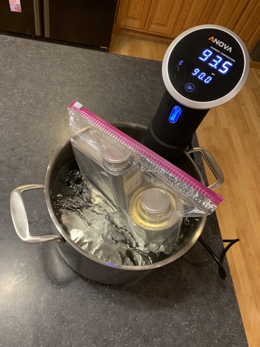
So I filled all the small bubbles with gelcoat, sanded them down flush with the mold surface, and all was well. I'm glad that all the defects were on the trim-able part of the mold. To prep the mold, I again used the Mcguires #8 mold release wax. 4 or 5 layers applied over a week or so. Then, I sprayed the mold with a mist coat of PVA. The edges are masked off so that the vacuum bag sealant tape will stick. Here is it all shiny and ready for the infusion:

The epoxy I'm using is Adtech 820/823 for its low viscosity of 350cps. It has a minimum cure temp of 75F or so with a pot life of about 45 minutes. But, you can get an even lower viscosity by elevating the temperature, but this comes with a shorter pot life and shorter cure time. I'm not heating the whole house up to 90 degrees, but I did preheat the resin to 90F and it worked very well. I also had a heating pad under the mold on low- to keep the mold temp around 90-100F.


The epoxy I'm using is Adtech 820/823 for its low viscosity of 350cps. It has a minimum cure temp of 75F or so with a pot life of about 45 minutes. But, you can get an even lower viscosity by elevating the temperature, but this comes with a shorter pot life and shorter cure time. I'm not heating the whole house up to 90 degrees, but I did preheat the resin to 90F and it worked very well. I also had a heating pad under the mold on low- to keep the mold temp around 90-100F.
"Everybody needs beauty as well as bread; places to play in and pray in, where nature may heal and give strength to body and soul" -John Muir
03/12/2019 11:57PM
The infusion itself went like clockwork. All the work on this project was in m making the mold. Start to finish it took me maybe an hour and a half to assemble the stack and infuse the part. The active infusion time was about 20 minutes before I clamped the lines and let it cure. The process is fairly specific, so I made a video to best explain it:
In case the embedded video doesn't work, here is a link.
The part cured overnight and I demolded it after 16 hrs. It released very easily from the mold, and there is no damage to the mold, so it can be re-used.


In case the embedded video doesn't work, here is a link.
The part cured overnight and I demolded it after 16 hrs. It released very easily from the mold, and there is no damage to the mold, so it can be re-used.


"Everybody needs beauty as well as bread; places to play in and pray in, where nature may heal and give strength to body and soul" -John Muir
03/13/2019 12:10AM
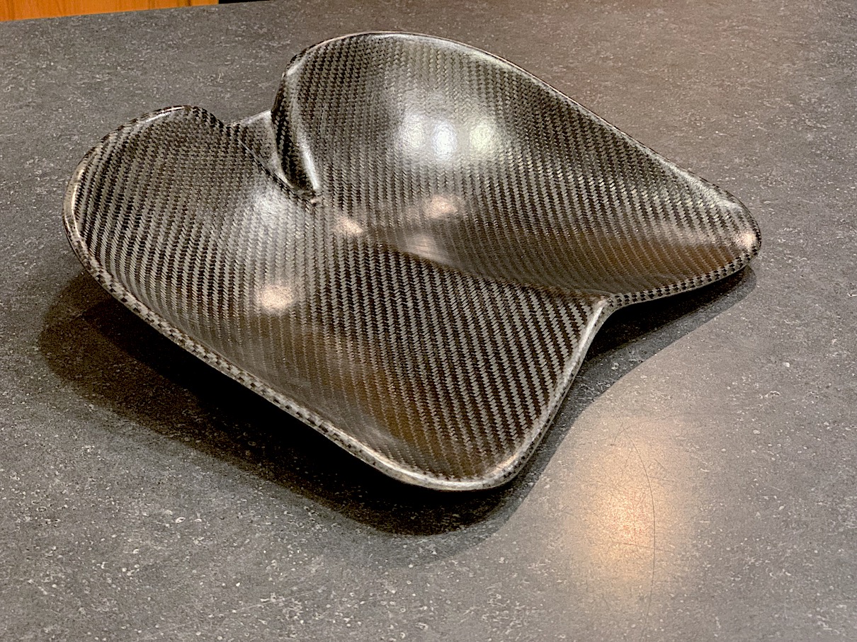
The surface finish of the part after demolding was perfect. Not a super shiny gloss, but it matched exactly the original surface I sanded/ polished on the plug. No dry spots or pinholes- it really came out well. 
I trimmed it with the band saw and filed the edges to get the final seat. It weighs about 8.7 oz.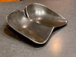
Now because I have the CAD file, I can find the exact surface area of the seat and use that to find out how much carbon and how much resin I used. Bear with me for a little math:
Surface area of seat from CAD file: .109144 m2
Weight of of 5.7oz carbon twill: 193.26 g/m2
Weight of of 21oz carbon twill: 712.02 g/m2
Total grams of carbon used: 176.519 g
Total weight of seat: 248.7 g
Calculated weight of resin: 72.18 g
Dividing the weight by specific gravity gives the volume.
Specific gravity of carbon fiber: 1.8 g/cc
Specific gravity of 820 resin: 1.1 g/cc
Calculated volume of Carbon fiber: 98.066 cc
Calculated volume of resin: 61.681 cc
Total Calculated volume of seat: 163.685 cc
Fiber/resin ratio by volume: 59.9%
The infusion process is supposed to target a 60% fiber ratio, so I was right on, and will have a very light and strong seat.
"Everybody needs beauty as well as bread; places to play in and pray in, where nature may heal and give strength to body and soul" -John Muir
03/13/2019 05:57PM
Wow. Thanks. Impressed. Seems like the learning curve is so steep (at least for me) but the video at least lets me see an all encompassing process.
What does your vacuum system cost? I've looked at doing CF paddles- but haven't gotten over the learning curve yet.
What does your vacuum system cost? I've looked at doing CF paddles- but haven't gotten over the learning curve yet.
03/14/2019 07:31AM
Nice work and thanks for sharing. 21 OZ fiber seems heavy but I'm sure you did your research and used what was needed. 8.7 OZ is a very impressive finished weight. I think I remember a traditional webbed ash seat weighing close to 2.5 LBS.
I Imagine when you mount the seat, getting the right tilt will make a big difference for being the most comfortable. Do you have any thoughts on that.
I Imagine when you mount the seat, getting the right tilt will make a big difference for being the most comfortable. Do you have any thoughts on that.
03/14/2019 08:16AM
THEGrandRapids: "Seems like the learning curve is so steep...
What does your vacuum system cost?"
The vacuum pump is a harbor freight special. The cheaper single stage one, I think. It draws a deep enough vacuum, but at a fairly low cfm flow rate. It works fine for small parts like this. The catch pot is made from 4” pvc pipe and some barbed fittings.
Composites don’t have to be complicated. Hand layup of fiberglass/Kevlar/carbon/etc is the most straightforward, but parts will be resin rich and thus heavier/weaker. Wet-layup and vacuum bagging is a little more advanced, and it gives a higher fiber/resin ratio, but is more tolerant of leaks/learning. Infusion requires mastery of vacuum bagging, plus managing resin viscosity and flow dynamics- but it gives an even higher fiber/resin ratio. Practicing each technique with small parts is invaluable learning!
"Everybody needs beauty as well as bread; places to play in and pray in, where nature may heal and give strength to body and soul" -John Muir
03/14/2019 08:31AM
wingnut: " Nice work and thanks for sharing. 21 OZ fiber seems heavy but I'm sure you did your research and used what was needed. 8.7 OZ is a very impressive finished weight. I think I remember a traditional webbed ash seat weighing close to 2.5 LBS.
I Imagine when you mount the seat, getting the right tilt will make a big difference for being the most comfortable. Do you have any thoughts on that."
Yeah I wasn’t sure how much carbon to use. Alan Gage said he had made seats with 2 layers of 21oz carbon, so that was my starting point. It seems stiff enough. You could probably get away with a thin foamcore and a little less carbon but the simplicity of a solid part is nice, and for a seat- I’m not sure the weight savings of a foam core would be worthwhile.
The geometry too, helps with stiffness. The curved surfaces will resist bending. That’s also the reason for the radiused ‘lip’ around the edge of the seat: The 30degree-or-so curved edge is more stiff than a flat edge.
As far as tilt goes, I think it’s going to involve a little trial and error to find what’s comfortable. I have a magic with a bench seat, so I may temporarily rig the custom seat on top at varied angles until I find the right spot. There is going to have to be some sort of bracket on the bottom of the seat to attach the slider tubes, and If I know exactly where it is supposed to be- I bet I could infuse it right along with the seat. Maybe version 2.0 will feature that.
"Everybody needs beauty as well as bread; places to play in and pray in, where nature may heal and give strength to body and soul" -John Muir
04/06/2019 10:10PM
Okay, time to make a pedestal. Wenonah uses welded aluminum angle for a frame. The easy homebuilt answer would be a wood frame with aluminum slider tubes. I want to experiment and learn, so a composite pedestal it will be. I modeled up the parts in CAD, and it really does appear simple.

Unlikle the monolithic seat, these parts have thickness and need some sort of a core. Core infusion can be done, but is even more tricky: you need to have a way to channel the resin underneath to the tool side of the core. The professional solution is foam with perforations or a grid score or channels or something- which is not easy or cheap to obtain. My first thought was that I could 3D print the core in a hollow honeycomb pattern and infuse carbon skins around it. I could model in resin flow channels and perforations and edge radiuses and it would be easy.

I printed half of a side support and found two problems. First, It is difficult to get fine geometry like the little flow channels to print watertight- the infusion resin would leak into a lot of the honeycomb cells. Second, to make it thick enough to hold up to vacuum pressure- the thing was far heavier than I expected and that just wouldn't do.
So foam it would have to be. I have been wanting to test different cores for a possible canoe build, so here is an opportunity to give it a shot and maybe get some good pedestal parts out of the deal. I was able to get ahold of some divinycell foam in both solid and cross-scored configuration. The solid one I drilled with 1/8" holes on a grid. I set up an infusion to test both types of foam, along with a few other things.
The outer layer is carbon/innegra, with a ply of plain innegra underneath, then core, and on the backside of the core is a layer of carbon.

I ran the infusion today without too much trouble, but I'm going to have to wait until tomorrow to demold and trim the parts to see if it worked.
"Everybody needs beauty as well as bread; places to play in and pray in, where nature may heal and give strength to body and soul" -John Muir
04/07/2019 07:15PM
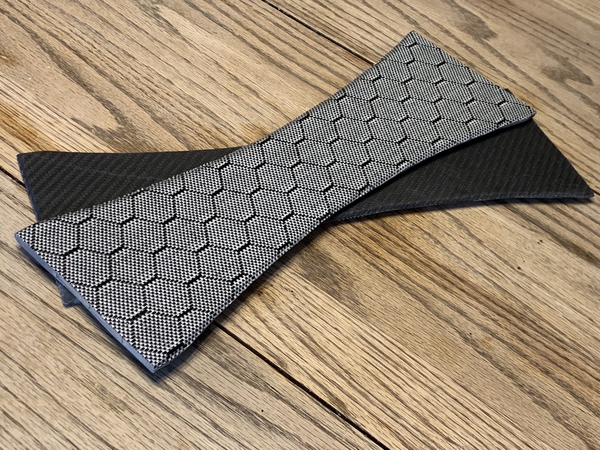
The parts trimmed out just fine. Innegra will fuzz when sanded, but not as much as kevlar. 
I was able to video both sides of my mold tool watch the flow front, but this meant my preheated tool cooled down to room temp quickly. I think this really slowed the last part of the infusion, but both parts did wet out just fine. The perforated one is 2.6oz and the cross-scored one is 17% heavier. It was very interesting to see the flow patterns on both.

Video of the infusion: ( https://youtu.be/tgNQn-Al6eQ )

I was able to video both sides of my mold tool watch the flow front, but this meant my preheated tool cooled down to room temp quickly. I think this really slowed the last part of the infusion, but both parts did wet out just fine. The perforated one is 2.6oz and the cross-scored one is 17% heavier. It was very interesting to see the flow patterns on both.
Video of the infusion: ( https://youtu.be/tgNQn-Al6eQ )
"Everybody needs beauty as well as bread; places to play in and pray in, where nature may heal and give strength to body and soul" -John Muir
04/07/2019 10:38PM
Arcola: "Do you think you'll be offering these as a drop in unit for sale? Little progress has been made in canoe seats IMO. Really nice work!"
Thanks, but nope. This hobby is to satisfy my curiosity.
A background goal is that I want to practice infusion enough where I will be comfortable attempting a full boat infusion all at once.
"Everybody needs beauty as well as bread; places to play in and pray in, where nature may heal and give strength to body and soul" -John Muir
04/08/2019 08:10AM
wingnut: " Thanks for sharing your work. The shape resembles the one Alan Gauge made for his boat. No doubt a good design. Are you thinking about CF tubes in place of aluminum tubing. "
Yep- Alan’s work was the inspiration here. CF tubes might be lighter, and are definitely the ‘high-tech’ option that matches the rest of the project so far. I don’t know what spec I need though: as to which wall thickness would be lighter than but just as strong as aluminum when loaded in 3-point bending. I already have aluminum tube, so I’ll likely go with that.
Something else I haven’t worked out yet is how to attach it to the canoe. I would like some mechanism to be able to remove the whole pedestal without leaving prominent hardware on the floor of the canoe. I could epoxy T-nuts into the core of the canoe, but I think they would be prone to getting clogged with sand and dirt. Perhaps a split hinge bracket with removable pin or something.
"Everybody needs beauty as well as bread; places to play in and pray in, where nature may heal and give strength to body and soul" -John Muir
08/12/2019 06:14PM
So the seat has spent the majority of the summer duct taped to the webbing seat in my magic solo to test heights/angles. I am building a canoe as a final destination for this seat, so it is time to finish the pedestal. For the end plates, I experimented this week with 3D printing a structural core without face layers. I think it worked well and was fairly lightweight. I cut out 1cm spaces and inset wooden blocks so that I have something to sink screws into to secure the slider tubes.

I then hand laminated some carbon fiber sheets (2 layers of 5oz carbon twill, bias and 0/90. Already cured from an infusion test- trimmed to fit the cores) with a back layer of carbon and front layer of innegra. I used about 80g of epoxy to put everything together, and put the wet stack under a simple vacuum bag to compress it all together.

The trick with this is to have the vacuum bag much larger than the parts, and firmly tape down the edges tight to a table. Apply the top bag film with tacky tape to get a seal, then firmly tape down the edges of the top bag. When you draw vacuum, the top/bottom bag film will both stretch down around the part and meet in the middle to form a seam centered on the edge of the part. Once full vacuum is drawn and everything is tight, you can cut the edges of the vacuum bag off the table: this lets the bag tighten the seam further.

After it cured, I trimmed the edges on the band saw. I still need to sand the edges smooth and then drill holes for the slider tubes. The "feet" will eventually be cut down flat to bond them to the floor of the canoe once I define the final seat height. Each end plate weighs about 80g.
"Everybody needs beauty as well as bread; places to play in and pray in, where nature may heal and give strength to body and soul" -John Muir
08/13/2019 01:52PM
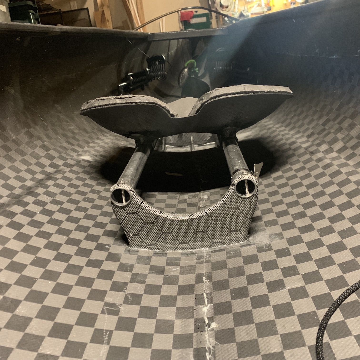
I drilled out the end plates and epoxied things together. It looks like a pedestal now.

I ended up cutting most of the feet off the end plates to lower the seat to the 6.5" height I'm comfortable with. Spacing between the longitudinal supports is just enough to fit a Nalgene bottle in between. I also made sure to leave enough space under the bars so I can clamp on the wenonah pedestal yoke if I want.

The bars are 1" aluminum tubing, and the slider tubes are cut from 1 1/4" HDPE irrigation tubing. It has an ID that slides perfectly on the aluminum tube.

I still have to drill screws to fix the aluminum tube. The seat is attached to the slider tubes with some epoxy and scrap wedges cut from the bottom of the end plates to hold the right angle. I can sit on it and it doesn't move, but I will plan to wrap the slider tubes in a layer of carbon to make it real strong.
What do you all use for a slider clamp?
"Everybody needs beauty as well as bread; places to play in and pray in, where nature may heal and give strength to body and soul" -John Muir
08/13/2019 08:20PM
Alan Gage: "That looks fantastic! What was the final weight?
To clamp them I use a hose clamp over one of the tubes with a washer welded to the screwdriver slot so that it can be finger operated.
Alan"
Thanks.
Pedestal + seat is 23.5oz. I just mixed another 30g of epoxy though, to wet some carbon scraps and reinforce the seat/slider tube connection. The aluminum tube adds a good chunk of weight. Tubes are 16” long and the slider tube is 5” so I have 11” of adjustment.
I’ve never used a pedestal-mount yoke, but the slider tubes are at 6” centers so I think I’m going to get one for this boat- the gunwales are far from parallel at the carrying point.
"Everybody needs beauty as well as bread; places to play in and pray in, where nature may heal and give strength to body and soul" -John Muir
09/02/2019 06:58PM
I ended up cutting apart the pedestal. The seat was a bit too high for the boat it went in,
and the "sides" of the pedestal interfered with the carrying yoke. So I epoxied the pedestal ends right to the canoe bottom and cut the sides into triangle support brackets. It seems solid, and brought the front edge of the seat down to 5" above the floor. Cutting that much off saved me about 10 oz.
I think most builders from this board are there also, but if you're curious about the boat, the build thread is here.

"Everybody needs beauty as well as bread; places to play in and pray in, where nature may heal and give strength to body and soul" -John Muir

Subscribe to Thread
Become a member of the bwca.com community to subscribe to thread and get email updates when new posts are added. Sign up Here
 Search BWCA.com
 Donate